 Tweet
Tweet
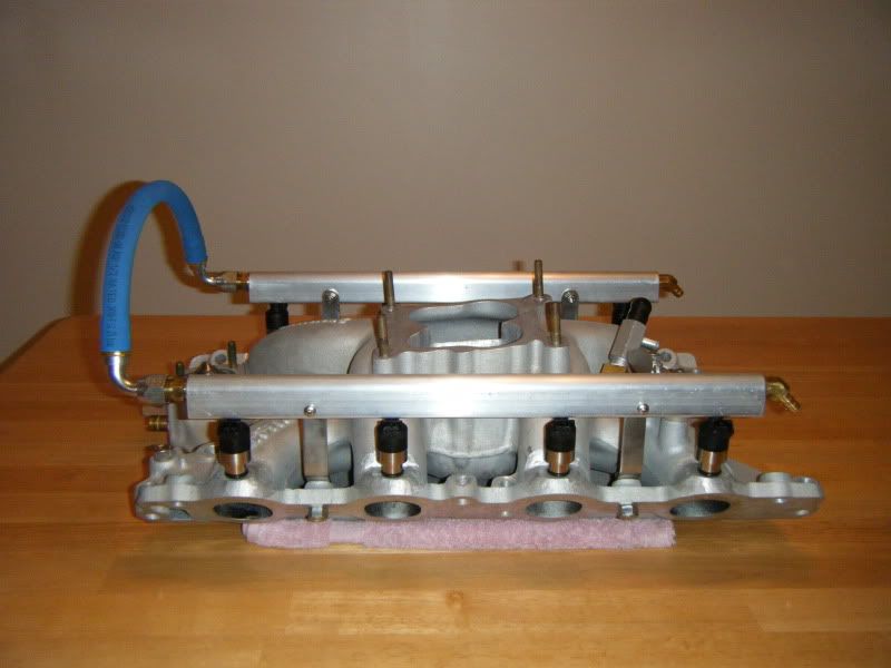
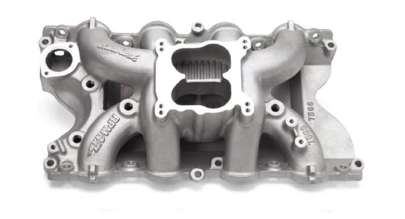
This is an Edelbrock Performer RPM 'Air-Gap' intake manifold which has been perfect for my engine combination. I'm not falling for the usual claim, "single-plane is acceptable, since it's now only flowing air." Airflow port dynamics still apply; big open plenums and short large runners aren't good for low to mid RPM torque (LINK). This is a heavy off-road truck and the engine must be built for such an application (LINK). Also, read the quote & video at the end of this post.
A wide & strong torque curve was the premise of this MPFI project. Unfortunately, many enthusiasts believe a single-plane intake manifold will make optimum power across the entire RPM range, when converted to a dry manifold (MPFI). This is simply not true. For example, GM's TPI & Ford's 5.0 SFI have wild looking, long runner intake manifolds and for good reason (wide power curve). In reality, single-plane manifolds are commonly used for MPFI conversions, simply because all eight runners end at the same height and angle; making the conversion much easier. Not so, on a dual-plane manifold; there's more work involved. I definitely wanted to retain my dual-plane manifold because it functions very well on my engine; it just required a little more engineering. Ironically, I think the way I did it, was easier than if I used injector bungs (cleaner look too).
Because it's a dual-plane manifold, there was a considerable amount of welding required to make the MPFI conversion possible. The runners are angled differently and at various heights. I wanted the injectors positioned at the very end of each runner and as low as possible. I don't like injector bungs, so the injector port drill bit from Ross Machine Racing was my best option for machining the manifold injector holes and the fuel rails.
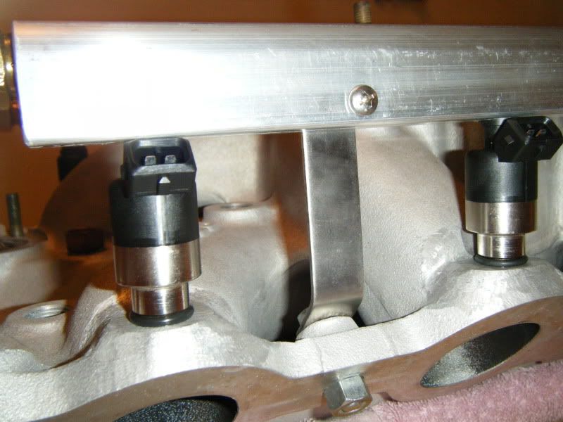
(NOTE: The additional visible o-rings on the bottom of each injector, are just there for supplemental support/dirt shield/gap aesthetics.)
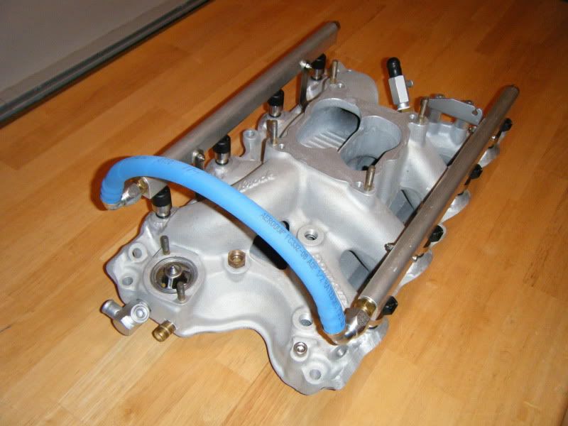
I also purchased blank fuel rails (1/2" I.D.) from Ross Machine Racing and machined them myself. I threaded the ends of the fuel rails to 3/8" NPT after enlarging the ends to 9/16" using a step drill bit. The fuel rail hold downs are made out of high grade, 1/8" thick stainless steel (difficult to drill) and are very rigid. The fuel rails are much easier to machine since they can be clamped in a drill press vise. The only issue I had was drilling & tapping the ends to 3/8" NPT because the I.D. of the rails is 1/2". You can't simply drill a 1/2" hole to the required 9/16" (for 3/8" NPT); the bit is too unstable. So I first made a pilot hole using a Unibit step-drill bit, then drilled the 9/16" hole in about 3/4" for tapping 3/8" NPT. I purchased 3' of Aeroquip -8AN AQP socketless hose with 90° swept fittings to assemble the single fuel rail crossover line/hose. The arch in the hose is there for distributor/cam sync unit access. My engine is blue & aluminum in color, so the intake manifold assembly looks great.
(NOTE: The Phillips head bolts were temporary fasteners. The permanent fasteners are stainless steel flanged fuel rail bolts, opposite side thick washers & nylon locknuts.)
The former TBI unit was converted to an MPI throttle body (1000 CFM) with extensive welding and porting. You can read about it in this LINK.
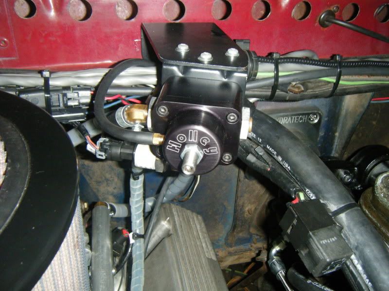
I'm using Holley EFI 66 lb/hr injectors with a Holley 512-504-5 fuel pressure regulator. Holley Dominator EFI system; dual WBO2 sensors,
dual knock sensors, fuel & oil pressure transducers, VSS sensor, a custom 60-2 crank trigger kit, and Holley Waste-Spark DIS.


Here's a picture of how/where I mounted the Holley 512-504-5 fuel pressure regulator & fuel pressure transducer:
NOTE: The additional o-rings you see on the bottom of each injector, are just there for gap aesthetics/dirt shield/supplemental support. (Now there's actually three o-rings on each injector.) The injector port holes are machined into the manifold just like OEM injector bungs. The injectors are o-ring sealed (top & bottom) as they were designed to be. Here's a video of how I machined the injector holes in the manifold & fuel rails: LINK.

FYI: I've been contacted in reference to the welding I did at the end of each runner, so let me clarify a few points. In order to machine the injector holes into the intake manifold, I needed eight equal height, flat platforms at the end of each runner. I aluminum welded enough material, where I was able to cut off the top of each weld, the exact same height. I did this by carefully sliding the manifold against a spinning die grinder cut-off wheel in a drill press.
(NOTE: Other home machining operations can be accomplished with various carbide burrs, cut-off wheels and a drill press.)
Afterwards, I ground each surrounding area smooth, contouring to the shape of each runner. The Alumacut carbide burrs from CarbideSelect.com are the best aluminum grinding burrs I've ever used! Once I had eight, nice looking flat bosses, it was a simple matter of machining the holes with the injector drill bit pictured above. This allowed me to install each injector into the manifold (just like you would if using injector bungs), but without using injector bungs. The money saved by not purchasing injector bungs, went toward the cost of the injector drill bit (which was still required for the fuel rails anyway).
Dyno comparison between Edelbrock single-plane & dual-plane intake manifolds:
https://www.youtube.com/watch?v=i2DvnoHWagk (Single-Plane vs Regular & RPM Dual-Plane vs Air-Gap Intake Manifolds)
A wide & strong torque curve was the premise of this MPFI project. Unfortunately, many enthusiasts believe a single-plane intake manifold will make optimum power across the entire RPM range, when converted to a dry manifold (MPFI). This is simply not true. For example, GM's TPI & Ford's 5.0 SFI have wild looking, long runner intake manifolds and for good reason (wide power curve). In reality, single-plane manifolds are commonly used for MPFI conversions, simply because all eight runners end at the same height and angle; making the conversion much easier. Not so, on a dual-plane manifold; there's more work involved. I definitely wanted to retain my dual-plane manifold because it functions very well on my engine; it just required a little more engineering. Ironically, I think the way I did it, was easier than if I used injector bungs (cleaner look too).
Because it's a dual-plane manifold, there was a considerable amount of welding required to make the MPFI conversion possible. The runners are angled differently and at various heights. I wanted the injectors positioned at the very end of each runner and as low as possible. I don't like injector bungs, so the injector port drill bit from Ross Machine Racing was my best option for machining the manifold injector holes and the fuel rails.
(NOTE: The additional visible o-rings on the bottom of each injector, are just there for supplemental support/dirt shield/gap aesthetics.)
I also purchased blank fuel rails (1/2" I.D.) from Ross Machine Racing and machined them myself. I threaded the ends of the fuel rails to 3/8" NPT after enlarging the ends to 9/16" using a step drill bit. The fuel rail hold downs are made out of high grade, 1/8" thick stainless steel (difficult to drill) and are very rigid. The fuel rails are much easier to machine since they can be clamped in a drill press vise. The only issue I had was drilling & tapping the ends to 3/8" NPT because the I.D. of the rails is 1/2". You can't simply drill a 1/2" hole to the required 9/16" (for 3/8" NPT); the bit is too unstable. So I first made a pilot hole using a Unibit step-drill bit, then drilled the 9/16" hole in about 3/4" for tapping 3/8" NPT. I purchased 3' of Aeroquip -8AN AQP socketless hose with 90° swept fittings to assemble the single fuel rail crossover line/hose. The arch in the hose is there for distributor/cam sync unit access. My engine is blue & aluminum in color, so the intake manifold assembly looks great.
(NOTE: The Phillips head bolts were temporary fasteners. The permanent fasteners are stainless steel flanged fuel rail bolts, opposite side thick washers & nylon locknuts.)
The former TBI unit was converted to an MPI throttle body (1000 CFM) with extensive welding and porting. You can read about it in this LINK.
I'm using Holley EFI 66 lb/hr injectors with a Holley 512-504-5 fuel pressure regulator. Holley Dominator EFI system; dual WBO2 sensors,
dual knock sensors, fuel & oil pressure transducers, VSS sensor, a custom 60-2 crank trigger kit, and Holley Waste-Spark DIS.
Here's a picture of how/where I mounted the Holley 512-504-5 fuel pressure regulator & fuel pressure transducer:
NOTE: The additional o-rings you see on the bottom of each injector, are just there for gap aesthetics/dirt shield/supplemental support. (Now there's actually three o-rings on each injector.) The injector port holes are machined into the manifold just like OEM injector bungs. The injectors are o-ring sealed (top & bottom) as they were designed to be. Here's a video of how I machined the injector holes in the manifold & fuel rails: LINK.
FYI: I've been contacted in reference to the welding I did at the end of each runner, so let me clarify a few points. In order to machine the injector holes into the intake manifold, I needed eight equal height, flat platforms at the end of each runner. I aluminum welded enough material, where I was able to cut off the top of each weld, the exact same height. I did this by carefully sliding the manifold against a spinning die grinder cut-off wheel in a drill press.
(NOTE: Other home machining operations can be accomplished with various carbide burrs, cut-off wheels and a drill press.)
Afterwards, I ground each surrounding area smooth, contouring to the shape of each runner. The Alumacut carbide burrs from CarbideSelect.com are the best aluminum grinding burrs I've ever used! Once I had eight, nice looking flat bosses, it was a simple matter of machining the holes with the injector drill bit pictured above. This allowed me to install each injector into the manifold (just like you would if using injector bungs), but without using injector bungs. The money saved by not purchasing injector bungs, went toward the cost of the injector drill bit (which was still required for the fuel rails anyway).
Originally posted by Doug Flynn - Chief EFI Engineer @ Holley
https://www.youtube.com/watch?v=i2DvnoHWagk (Single-Plane vs Regular & RPM Dual-Plane vs Air-Gap Intake Manifolds)